Mirrotron Control System Overview
Table of Contents
- Software Repositories
- Overview
- Mirrotron application server
- RF source (LLRF)
- Timing system
- 200 MHz RF power amplifier
- Vacuum system
- Cooling system
Software Repositories
- Mirrotron Application Server
- Mirrotron Users guide
- RF Frequency Source
- Four Quadrant IQ Phase Detector
- Timing Gate Generator
- RFQ LLRF Timer Cube
- IQ Monitor System
- RF Power Monitor System
- RF Power Amplifier System
- RFQ Vacuum System
- RFQ Vacuum System Cube Controller
- Backing Pump System
- RFQ Inlet Temperature Tray
- RFQ Outlet Temperature Tray
- RFQ Flow Cube
- RFQ Inlet Flow Tray
- RFQ Outlet Flow Tray
Overview
(contents)
The Mirrotron Radio Frequency Quadrupole (RFQ) is part of a compact neutron source that is being built in Martonvásár Hungary. The compact neutron source consists of five major systems
- 35 keV Hydrogen Ion source
- 2.5 MeV RFQ
- Lithium Target station
- Neutron Instrument stations
The 2.5 MeV RFQ designed and built by Time Co, Ltd., Japan is a pulsed accelerator that can support 1.25 mS pulses at a rate of 40 Hz for a maximum duty factor of 5% . The RFQ can accelerate a peak beam current of 20 mA with an input RF power 260 kW at 200 MHz. providing an average beam power of 2.5 kW. The loaded cavity Q is 10,000 which results in a cavity bandwidth of 20 kHz.
Mirrotron application server
(contents)
The server for a Mirrotron control system is derived from the Blinky-LiteTMBox. The box can be instantiated on a small computer inside a firewall such as Raspberry Pi 3B+ which is more than adequate for a medium size control system or can be hosted in the cloud.
The primary tasks of the box are to:
- Subscribe to the messages from all of the trays in the system
- Scan each message for alarm notifications and notify alarm system
- Store the latest messages from in the tray database
- Archive a message when appropriate
- Serve applications to users
The box consists of three components that can reside on the same computer or separate (cloud) computers
- Application server
- MQTT Broker
- System database
The configuration that provides data to the Mirrotron application server can be divided into 5 major subsystems
RF source
(contents)
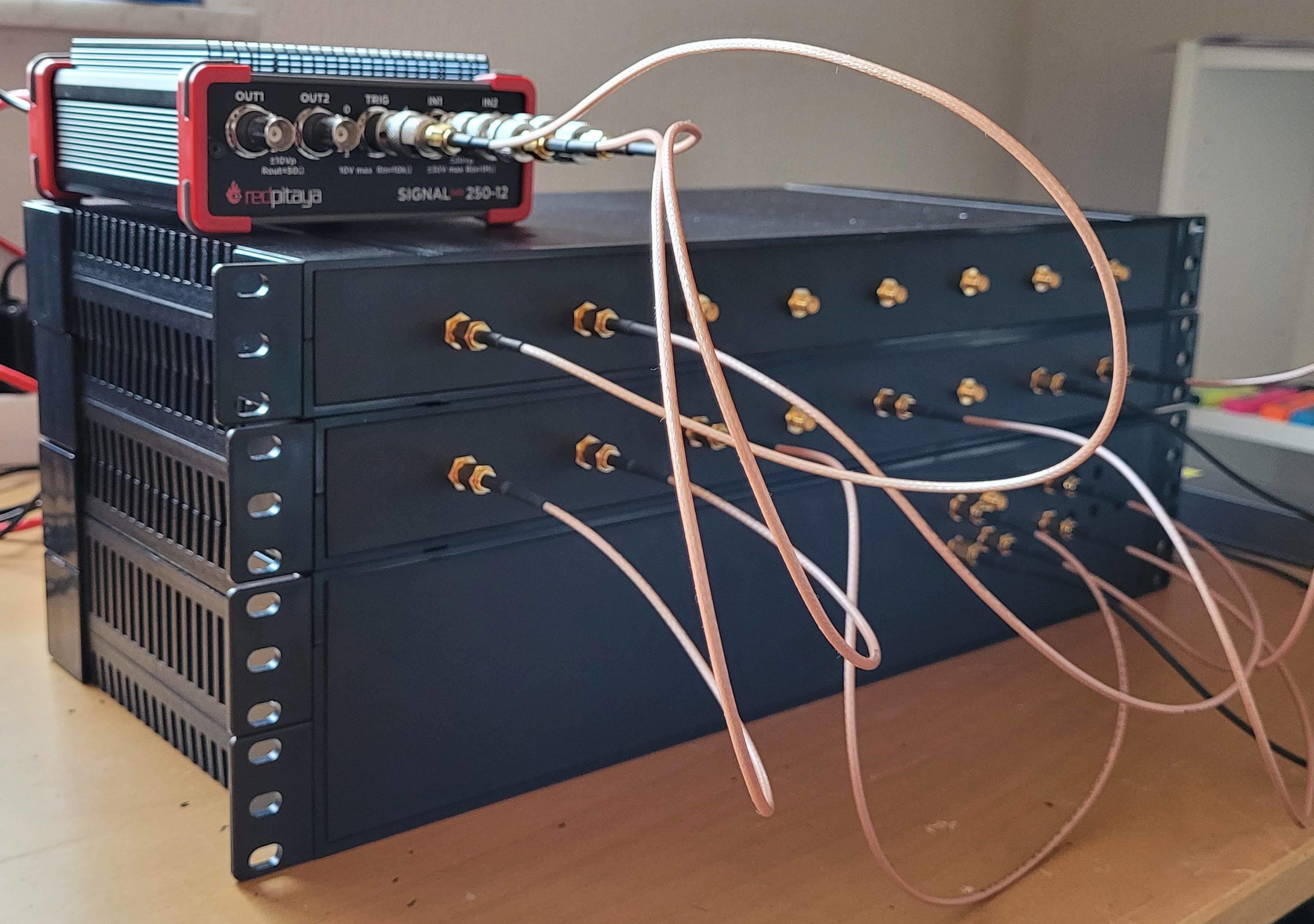
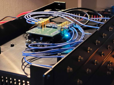
The RF source is a modular system based on the Red-Pitaya Stemlab 125-14 re-configurable instrument platform. A modular approach was chosen for design simplicity and future upgrades. Likewise, the Red-Pitaya Stemlab 125-14 was chosen for its ease of use. A block diagram is shown in Figure 1. The LLRF system comprises of four modules:
Figure 1. Block diagram of LLRF
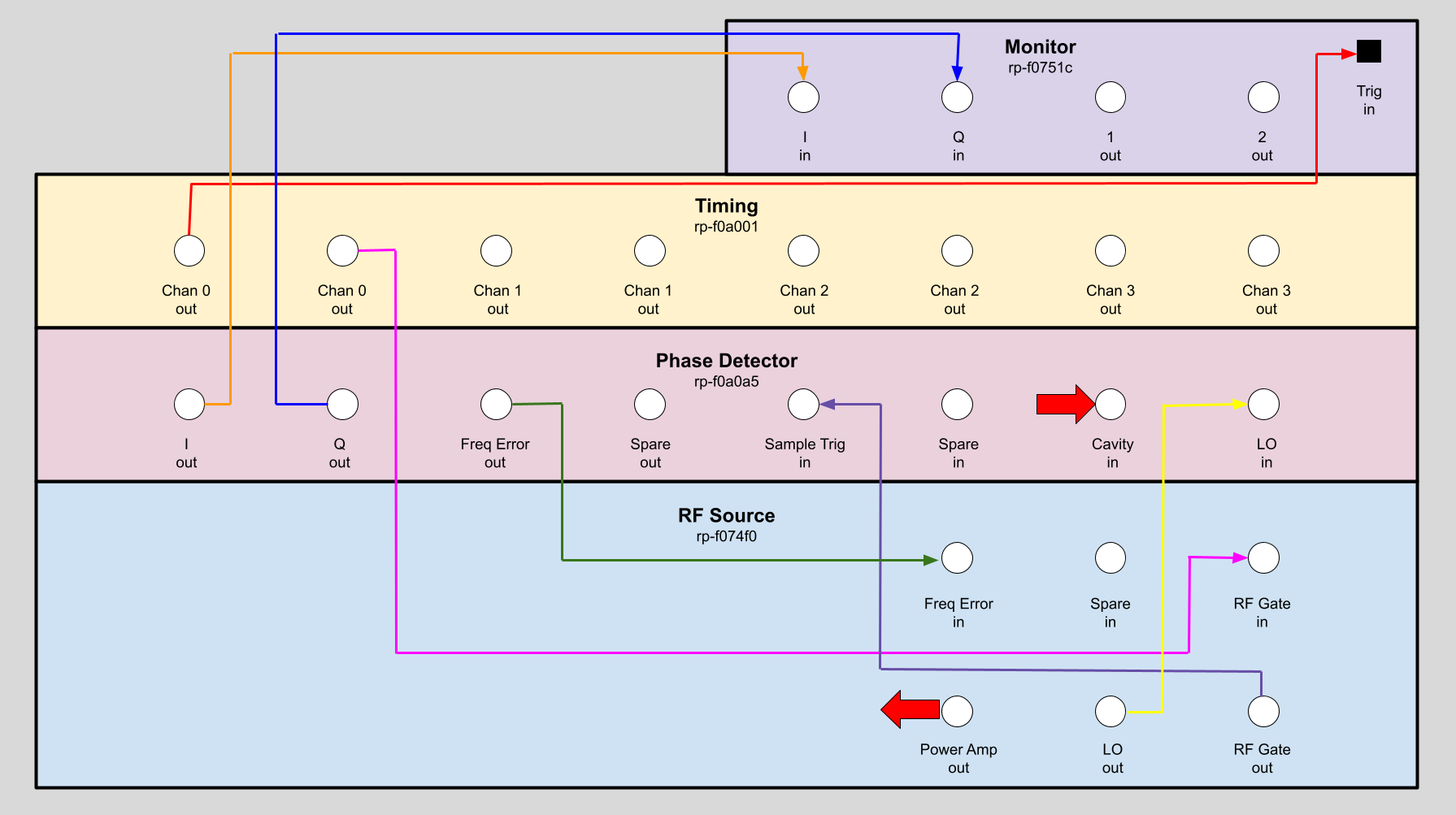
Figure 2. LLRF modules Implementation
Timing system
(contents)
The Mirrotron RFQ is a pulsed system so a timing system is required. The Mirrotron Timing system is an 8 channel system based on a 32 bit counter clocked at 125 MHz. The resolution of the timing system is 8nS and can have intervals as long as 17 seconds. The implementation is shown in Figure 3.
Channel allocation
The Mirrotron RFQ uses five of the eight channels:
- Channel 0 for the RF source and phase Detector
- Channel 1 for LLRF scope
- Channel 2 for the RF Power Amp pulse gate
- Channel 3 for the RF Power Amp sample and hold
- Channel 4 for the RF Power Amp Scope
Easy Setup Timer
These channels can be configured with the Timing App as shown in Figure 30. To change the pulse length of the RFQ, all five channels would need to be adjusted which would be time consuming and error prone. To make it easier to change the pulse length a virtual tray called the Easy Setup Timer was created. This virtual tray will adjust all five channels synchronously. This virtual device is implemented in the Mirrotron application server.
Figure 3. Gate Generator Implementation
200 MHz RF power amplifier
(contents)
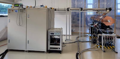
The RF Power amplifier is custom made solid state RF power amplifier operating at 200 MHz. The amplifier has a gain of about 75 dB and can transform 10mW (10dBm) of RF signal into 320 kW of RF power. The amplifier can operate a pulse length of 1.25mS at a pulse repetition rate of 40 Hz. The RF Power amplifier connected to the RFQ is shown in Figure 4.
The RF power amplifier requires two timing channels from the Timing system.
- Channel 2 for the RF Power Amp pulse gate
- Channel 3 for the RF Power Amp sample and hold
The RF power amplifier takes the low level signal generated from the RF source as shown in Figure 1. The amplifier has a 75dB directional coupler mounted on its output and the forward and reflected RF signals are available on the front panel. These signals are fed into the RF power monitor.
The manufacturer of the RF power amplifier provides a remote interface so the RF Power amplifier can be controlled and monitored.
Figure 4. RF power amplifier connected to RFQ
Vacuum system
(contents)
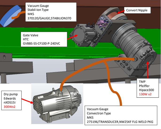
The RFQ requires ultra-high vacuum for operations. RF power should not be applied to the cavity unless the vacuum pressure inside the cavity is less than 5x10⁻⁵ Pa. The RFQ has two identical vacuum systems mounted on either side of the RFQ as shown in Figure 5. The RFQ vacuum system tray is responsible for:
- Control opening and closing of valves
- Read status of gate valve limit switches
- Read vacuum gauge pressures
- Read status of the turbo pumps
- Turbo pump error status
- Turbo pump 70% speed status
- RFQ Vacuum protection
The backing pump trays are responsible for:
- Controlling backing-pump power on and off.
- Reading backing-pump status
- Pump speed
- Pump Temperature
- Pump hours
- Pump cycles
Figure 5. Vacuum system layout
Cooling system
(contents)
The RFQ will dissipate energy at an average rate of 15kW when running at peak RF power and 5% duty factor. To keep the remove this energy, two water chillers supply cooling water to the upstream (inlet) and downstream (outlet) ends of the RFQ. The cooling water flows into headers that split the cooling to various cooling channels built into the RFQ. Control of the water chillers is manual and not part of the control system.
However to ensure that water is flowing at the correct flow rate and temperature, a separate temperature monitor and flow monitor is mounted on each cooling channel on each header as shown in Figure 6. On top of each header, as shown in Figure 7, are mounted custom built Blinky-LiteTM trays that measure and report the temperature and flow through each cooling channel to the control system.
Details about the cooling monitor system software and electronics can be found at:
Figure 6. Cooling System Header
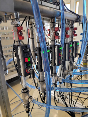
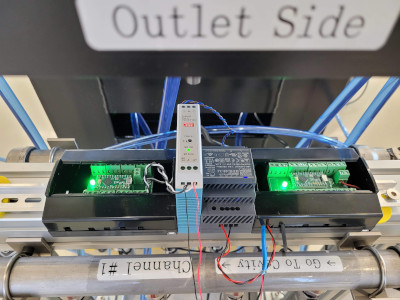
Figure 7. Outlet Cooling System Header
From left to right: Temperature cube and tray, 5V power, 24V power, Flow cube and tray
